
I started this Raspberry Pi WiFi RC Car project a while back when i picked up a barely used hobby grade RC from a flea market. The one I got did come with a transmitter which was perfect for my Raspberry Pi WiFi RC Car project. For the price of a multi-channel and multi-frequency transmitter I can probably build 2-3 of these projects.
This is my first version so there are things that needs to be fine tuned and plenty of improvements are possible. My daughter was also very interested in this project and helped me test drive the car. In this post I will cover soup to nuts on how to build this project.
I picked up a Raspberry Pi 2 board since it was the cheapest full blown computer I could buy, and wanted to learn and create something fun in this process. You can read my post about Raspberry Pi 2 and Arduino Tre boards Comparison. I have seen few RC Car projects on the web but they either were ESC (electronic speed controllers) based or 4 motor robotic type projects.
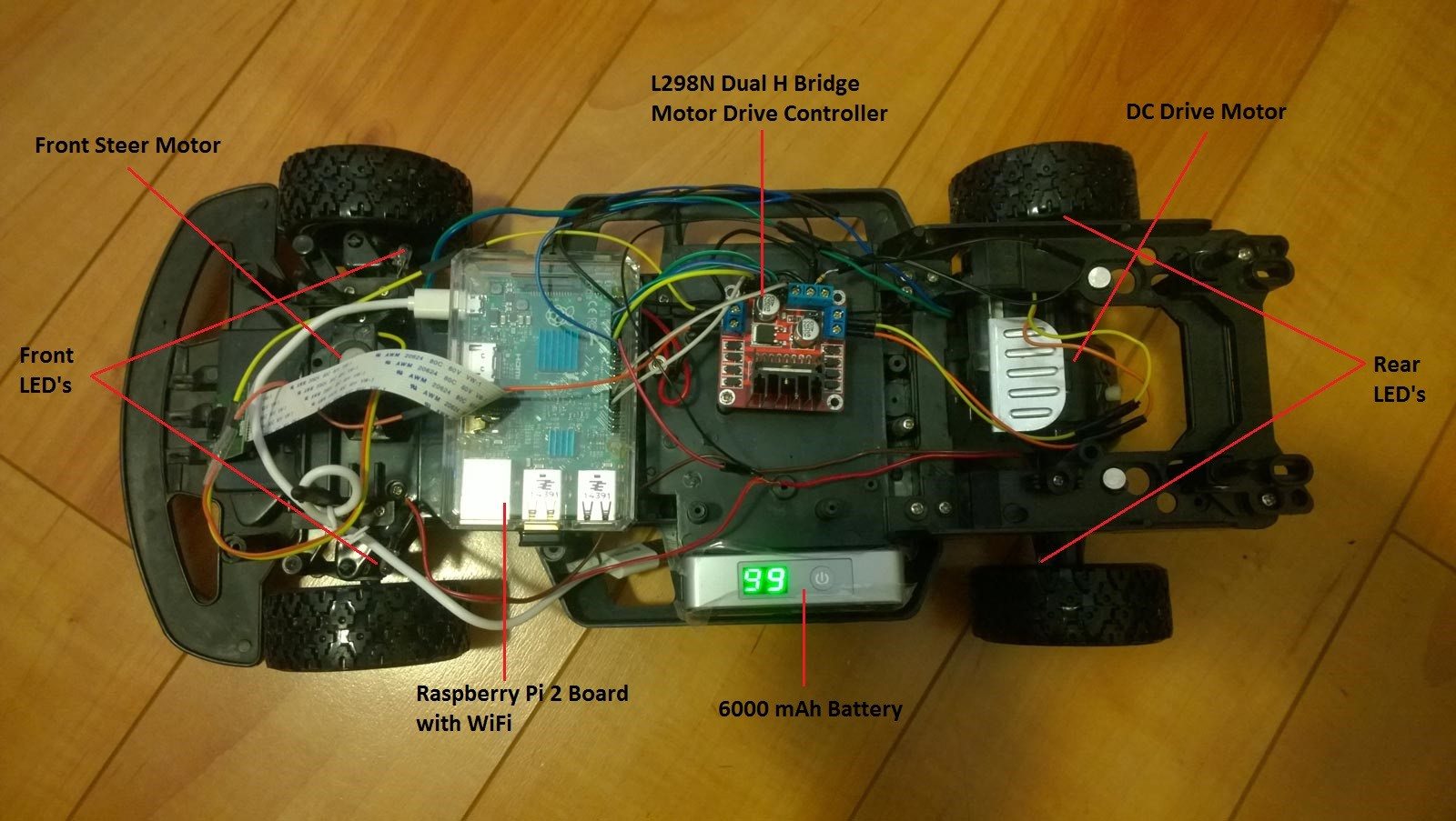
This is how the Raspberry Pi WiFi RC Car project looks like.

Hardware Requirements:
- Eachine Mini Y5 6000mAH Battery Bank
- Jumper Wires
- HDMI Cable
- HDMI Monitor
- Resistors
- LED’s
You can buy the Raspberry Pi 2 board individually or buy a starter kit that will contain everything including the Raspberry Pi 2, Case, SD Card, WiFi Adapter, LED’s, Jumper Wires HDMI Cable, Resistors, Breadboard and Heat Sinks. A starter kit is probably a good place to start IoT projects.
Here are some of the Raspberry Pi 2 Kits that you can buy from Amazon:
- Raspberry Pi 2 Ultimate Camera kit includes over 40 components and Pi Camera – http://amzn.to/1OEFvCA
- Raspberry Pi 2 CanaKit Ultimate Starter Kitincludes over 40 components – http://amzn.to/1LPVK0G
- Raspberry Pi 2 Complete Starter Kit includes Edimax Wi-Fi Adapter, Kingston 8GB Micro SD, Case, Heat Sinks, Power Supply and HDMI Cable – http://amzn.to/1G7usRh
- Raspberry Pi 2 Basic Starter Kit includes Pi 2 Board, Clear Case, 2 Amp Power Supply – http://amzn.to/1KblYmU
- Microsoft IoT Pack for Raspberry Pi 2 – http://www.adafruit.com/windows10iotpi2
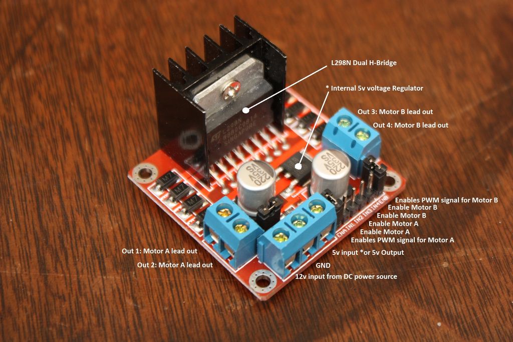
Why the L298N Motor Drive Controller Dual H-Bridge?
L298N Motor Drive Controller Dual H-Bridge is the key component of my Raspberry Pi WiFi RC Car which powers all the motors and sends signal to controls the direction and speed of the motors. This controller can drive 2 motors with PWM (Pulse Width Modulation) signal. PWM in itself is a vast topic so we won’t cover it here. Think of this as a technique to control the amount of power going through pretty much anything you want. In our project we are using it for controlling the speed of the motors and the brightness of the LED’s.
This module is integrated with one internal 5V power supply, meaning when your input voltage is 7V-35V, it makes 5V of energy board power supply logically; this 5V can be used to power another component.
Software Requirements
- Raspbian Wheezy (This is the Linux OS flavor) – http://bit.ly/1KWbtrE
- WiringPi (This is used to see all the GPIO’s) – http://bit.ly/1DIFwkR
- WebIOPi (For developing web apps) – http://bit.ly/1GsnctO
- PiCar Script (This is my custom scripts and UI files) – http://bit.ly/1jKk87n
- Fritzing – (For creating wiring schematics) – http://bit.ly/1jOBcTZ
- Weaved IoT Kit (For controlling the device from anywhere) – http://bit.ly/1TQ5UlR
Understanding GPIO Pins
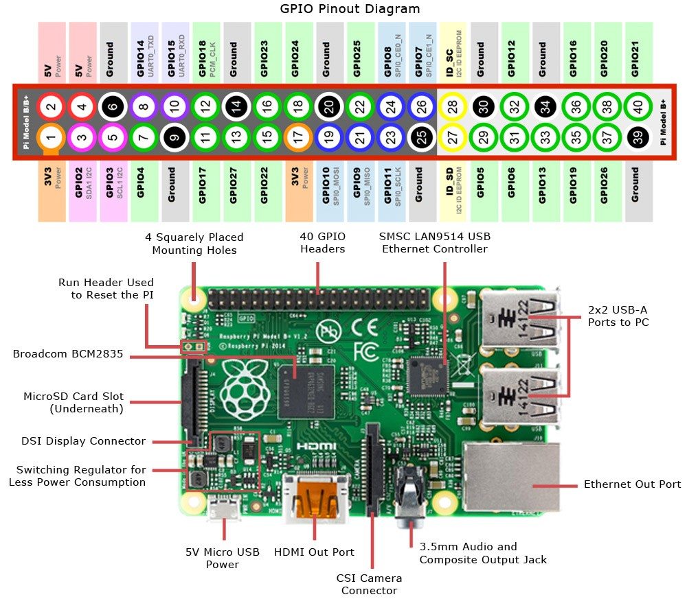
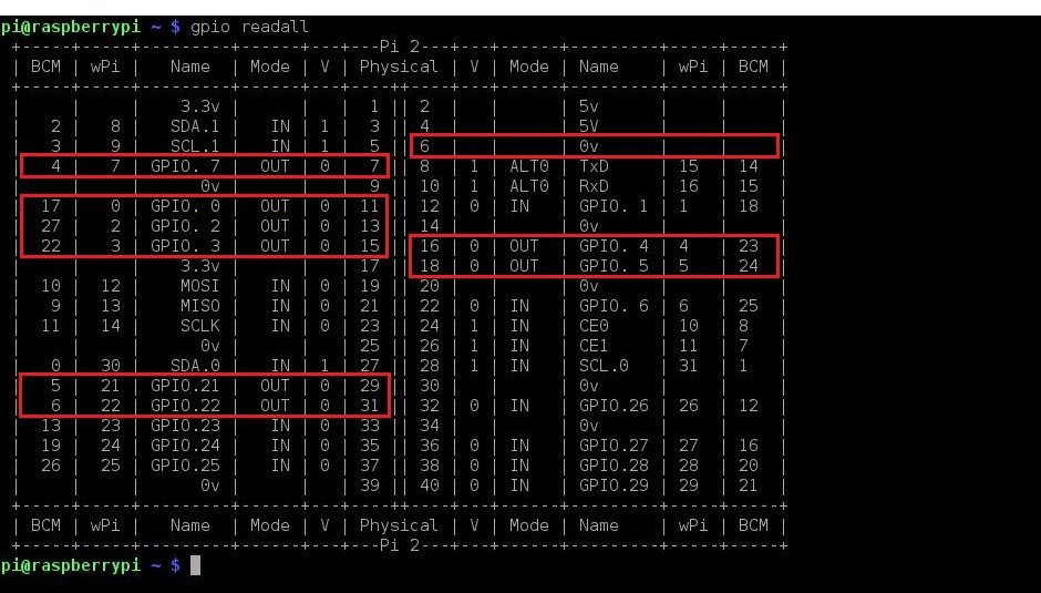
In order to correctly complete the wiring we need to understand the Raspberry Pi 2 GPIO pins which are used to connect various components to the Pi. These pins send the signals to the components connected, which could be turning on a light to driving a motor or reading data from a temperature or proximity sensor.
The ones highlighted in green are the 17 basic GPIO pins which is what we are going to use in our project. These pin can be configured in either input or output mode.
Most of the pins go directly to the processor chip so it is very important to carefully attach the components. A multimeter is going to be your best friend for any electronics or IoT project as mistakes in wiring or short circuits can permanently damage your Pi.
Wiring the Components
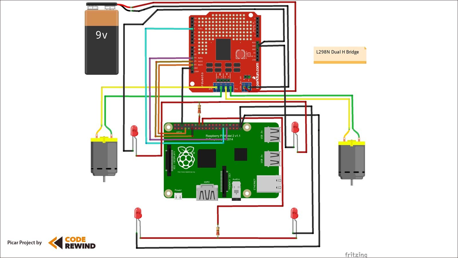
If you look at the above wiring you will notice that i connected the 9V supply to the L298N Dual H Bridge which will further power up the 9V Motors. Now, you may ask why do i need this additional component to power motors. Can I connect the motors to the Raspberry Pi GPIO pins? The answer is yes and no. The reason why we rely on a motor drive controller is because this can handle two motors up to 35V. Raspberry Pi only sends a maximum of 3.3V as its high signal. It not only provides enough power but controls direction and speed as i explained earlier.
I connected the Anode (+ve) of 2 sets of LED’s for left and right turn signals with one 330Ω resistor each. Resistors help keep the amount of current passing through the LED’s at a correct level, otherwise you could burn out the LED very quickly.
| Components | Header Pin | BCM Pin |
|---|---|---|
| Motor 1 Forward (IN1) | Pin 7 | Pin 4 |
| Motor 1 Reverse (IN2) | Pin 11 | Pin 17 |
| Motor 1 PWM (ENA) | Pin 29 | Pin 5 |
| Motor 2 Left (IN3) | Pin 13 | Pin 27 |
| Motor 2 Right (IN4) | Pin 15 | Pin 22 |
| Motor 2 PWM (ENA) | Pin 31 | Pin 6 |
| Left Turn LED | Pin 16 | Pin 23 |
| Right Turn LED | Pin 18 | Pin 24 |
| Common Ground | Pin 6 | – |
Installing and Configuring Prerequisites
- Format the SD card and install Raspbian Wheezy using Noobs or directly – https://www.raspberrypi.org/help/noobs-setup/
- Update your Raspberry Pi using the script by Rob Seder
- Install the WiFi adapter and connect to your wireless network
- Now install WiringPi using the following commands
-
sudo apt-get install git-core
sudo git clone git://git.drogon.net/wiringPi
cd wiringPi
sudo git pull origin
sudo ./build
- To use WiringPi to help you make proper GPIO connection type the following commands
-
gpio -v
gpio readall
This will display all the GPIO pin names, current mode, header pin numbers, BCM pin numbers and wPi equivalent pin numbers. In this project we have used the BCM pin numbering to send signal to various GPIO pins. Note down the BCM pin numbers for the physical pin numbers you have connected your wires.
Why WebIOPi Framework
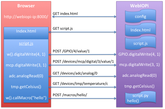
WebIOPi includes an HTTP server that provides both HTML resources and a REST API to control things. Your browser will first load a HTML file, then the included JavaScript will make Asynchronous calls to the REST API to control and update the UI. This method is very efficient, because it doesn’t need to refresh and download the whole page.
- This framework is written in Python, with facilities to load and execute custom script, using a comprehensive structure with setup and loop functions.
- Control, debug, and use your Pi’s GPIO, sensors and converters from a web browser or any app
- JavaScript/HTML client library to make Web UI
- Python/Java clients, to make Pi-to-Pi systems or Android applications
- You can extend the WebIOPi behavior by loading custom Python script using an Arduino like syntax with setup/loop functions
To install WebIOPi type the following commands
$ sudo wget http://sourceforge.net/projects/webiopi/files/WebIOPi-0.7.1.tar.gz/download
$ sudo tar xvzf WebIOPi-x.y.z.tar.gz
$ cd WebIOPi-x.y.z
$ sudo ./setup.sh
To start webiopi service with verbose output and the default config file. This is recommended when developing and debugging your scripts.
$ sudo webiopi -d -c /etc/webiopi/config
You can also start/stop the background service, the configuration will be loaded from /etc/webiopi/config.
$ sudo /etc/init.d/webiopi start
$ sudo /etc/init.d/webiopi stop
//To check if the service is running or not
$ sudo /etc/init.d/webiopi status
Once you are done building your project you should put this service to auto start when the Pi boots. To manage service at boot here are the commands.
//To setup your system to start webiopi at boot:
$ sudo update-rc.d webiopi defaults
//To remove webiopi start from boot:
$ sudo update-rc.d webiopi remove
To access the pi over local network open a browser and navigate to http://ipAddressOfPi:8000/ from any device in your network. Make sure to type the ip address of the Pi in the url. Default user “webiopi” and password is “raspberry“. The basic configuration required is to tell where our custom python script will reside which can be done by editing the config file under HTTP section using the following command.
$ sudo nano /etc/webiopi/config

//This is the section of the config that you will edit, mainly the doc-root and welcome-file attributes.
[HTTP]
enabled = true
port = 8000
doc-root = /home/pi/picar
welcome-file = index.html
Download the PiCar Project Source
If you look at the python file in the folder you will find that i am setting few constants at the beginning and then defining internal functions. Along with that i am registering few macros that will be called by the html page using JQuery calls.
def setup(): //This is the default setup function
def initiate(): //Initializes global variables
def forward(): //Custom internal function to control forward drive
def reverse(): //Custom internal function to control reverse drive
def  left(): //Custom internal function to control left turn
def  right(): //Custom internal function to control right turn
def flashAll(): //Custom internal function to flash led's
Now in the HTML page at the top i defined JavaScript functions which calls the python macros and are bound to the onmousedown event of the div container that holds the control images. Here is the script.
Finally, this section builds the User Interface


Download the complete PiCar Project Source
This was my first attempt at a complete IoT project from scratch so there is definitely room for many improvements. Some of the future improvements that I have in mind are.
- Adding Telemetry Support – includes reading temperature, speed of the motors, real time battery status
- Low Battery Notification
- Integrate Pi Camera Module
- Remove UI lag and make it more responsive
- Allow Device Accelerometer
- Return to Home – Engages the car in auto pilot mode and return to where it started
Connect from Anywhere
If you want to connect to your Raspberry Pi easily and securely from anywhere, you can install a service called Weaved. You will need to create a developer account on weaved before installing the service. You can choose from the SSH, HTTP, VNC, WebIOPi or even a custom TCP service on your port.
Conclusion
I hope you enjoyed this post and will try to build something interesting. Let me know what you think about this project and if you would like to help me out with the next release.
If you like our content, please consider sharing, leaving a comment or subscribing to our RSS feed to have future posts delivered to your feed reader.
Please follow us on twitter @CodeRewind and like us on facebook


how did you get webiopi to bring up the interface screen where you can control the rc car? i can get webiopi installed and i can get to the login page off my computer once the car to powered on but i cant get your pi car controls to show up on the page